
Most people mean VSWR when they say SWR. It is the ratio of maximum to the minimum voltage on a transmission line, which generally includes standing waves.
SWR can be calculated from the reflection coefficient gamma (Γ), which is determined by the impedance mismatch between the feedline and the load.
The formula is:
SWR = (1 + |Γ|) / (1 − |Γ|)
Where the reflection coefficient Γ = (ZL − Z0) / (ZL + Z0), ZL is the load impedance, and Z0 is the characteristic impedance of the feedline (typically 50 Ω). As a practical example, if your antenna presents 100 Ω to a 50 Ω feedline, Γ = 0.333 and SWR = 2:1. If it presents 25 Ω, same result — SWR is symmetric around the system impedance.
Most hams rarely do this math manually, but understanding it clarifies how important a good match at the feed point really is. It also illustrates why a tuner at the radio doesn't actually fix the mismatch at the antenna — it just makes the radio happy. The feedline from the tuner to the antenna (or Balun) still sees the mismatch between the feedpoint impedance and the feedline impedance. The proper cure is a matching network or broadband impedance transformer (or Balun) located at the feed point.
Choose Watts Engineering Labs Baluns to get a broadband low-loss match to your antenna
Discover the Watts Engineering Labs difference! Professionally designed, built to Commercial quality standards.

SWR — Standing Wave Ratio — is a measure of how well your transmission line is matched to your antenna. When RF energy travels down your coax and encounters an antenna that isn't a perfect match, some of that energy reflects back toward the radio. Those forward and reflected waves interact to create "standing waves" on the feedline. SWR is the ratio of the maximum to minimum voltage of those standing waves. A perfect match gives you 1:1 — no reflected power, all energy delivered to the antenna. Higher ratios mean more reflected energy and a somewhat less efficient system. High SWR also means your rig will fold back or your amp will trip offline.
Choose Watts Engineering Labs Baluns to get a broadband low-loss match to your antenna
Discover the Watts Engineering Labs difference! Professionally designed, built to Commercial quality standards.
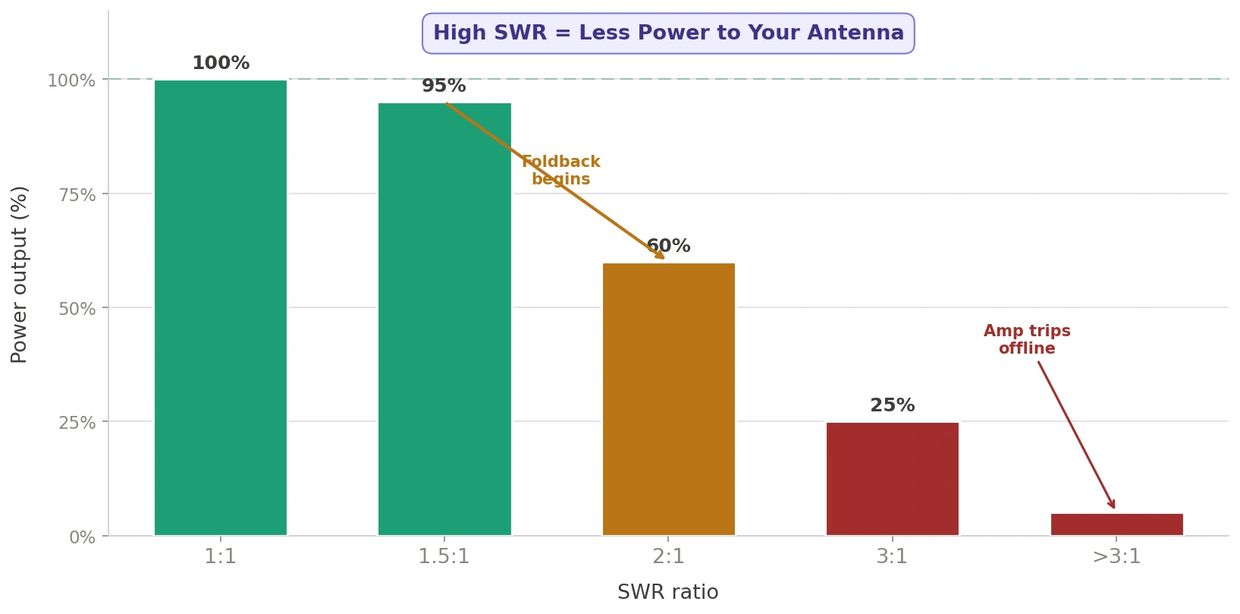
SWR matters because it has direct, practical consequences for your station's ability to operate. Most modern transceivers begin folding back power when SWR exceeds 2:1, and many amplifiers are even less tolerant — they'll trip offline or shut down entirely to protect themselves. That means high SWR isn't just an efficiency problem, it's an operational one. You may be trying to run 1500W and your amp will only deliver 400W before tripping offline.
Beyond foldback, high SWR increases feedline loss — power that should be going to your antenna is instead heating your coax. On receive, that same mismatch raises your noise floor and reduces sensitivity. The practical result is a station that can't run your desired power, transmits less effectively, and hears less clearly — all from a problem that's fixable at the antenna with a Balun or a matching section.
Choose Watts Engineering Labs Baluns to get a broadband low-loss match to your antenna
Discover the Watts Engineering Labs difference! Professionally designed, built to Commercial quality standards.

One improves SWR by better matching your antenna's feedpoint impedance to the feedline. This can be done with an impedance transformer or a matching network. Matching networks are narrow band by their nature, so they are fine for single-band antennas. However, matching a multiband antenna is more challenging and requires a broadband solution.
Broadband RF transformers provide this solution. If your antenna’s feedpoint impedance is different than your feedline’s characteristic impedance, you need a transformer whose output impedance is some ratio of the input impedance. If your antenna is balanced, you need a Balun (Balanced to Balanced) transformer. If your antenna is unbalanced, you need a Common Mode Choke, perhaps combined with an impedance transformer.
Dipoles are often matched with 1:1 Current Baluns.
Loops and Folded Dipoles are often matched with 4:1 Voltage Baluns, such as the Ruthroff. Voltage Baluns most often need to be used in concert with a good Common Mode Choke.
Off Center Fed Dipoles (OCFD), Loops, and Folded Dipoles are also often matched with 4:1 Hybrid Baluns, which provide more Common Mode Current Rejection (CMRR) than Voltage Baluns alone. They are equal to a Voltage Balun followed by a Common Mode Choke.
Beyond the Balun, antenna length trimming, feed point repositioning, and antenna tuners all play a role, but none of them substitute for a proper impedance match at the antenna.
Choose Watts Engineering Labs Baluns to get a broadband low-loss match to your antenna
Watts Engineering Labs baluns are designed, wound and measured to commercial standards, with real measured CMRR data — not spec sheet guesses.